Tinggalkan Pesan
Jika anda berminat dengan produk kami dan ingin mengetahui lebih lanjut, sila tinggalkan pesanan di sini, kami akan membalas anda secepat mungkin.

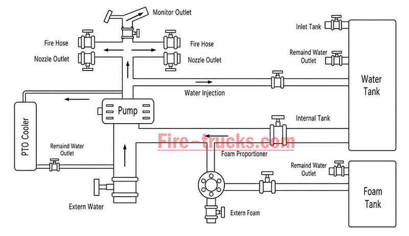
The fire truck PTO (Power Take-Off) is a power transmission device that transfers engine power to the fire pump. When the firefighter activates the PTO, mechanical power from the engine is transmitted through the transmission and PTO to the fire pump — this is the core working principle of how a fire fighting truck PTO system operates — enabling the pump to deliver high-pressure, high-flow water or foam without the need for a separate auxiliary engine.
Modern fire trucks typically use side-mounted PTO or full power PTO systems. These offer stable power output, convenient operation, and low maintenance costs, making them an essential component of the fire truck's firefighting system.
 Work")
PTO (Power Take-Off) is a critical component in the fire truck's power system. It is a gear transmission device installed between the engine and the transmission, designed to "divert" a portion of mechanical power from the vehicle's engine or transmission to the fire pump or other auxiliary equipment, without affecting the vehicle's normal driving capability.
The fire truck engine is originally responsible only for driving the wheels. However, once the fire truck arrives at the fire scene, the wheels no longer need power, while the fire pump requires power to draw and pressurize water. The PTO is the device that accomplishes this "power switch."

Power Take-Off (PTO) literally means "power output device."
On a fire truck, it refers to extracting rotational power from the engine flywheel or transmission gears through gear engagement, and delivering it to the fire pump or other auxiliary equipment.
Its name describes its function:
Engine = Power source
PTO = Power distributor
Fire pump = Power consumption end
Therefore, the PTO is the bridge connecting the "power source" and the "firefighting system."
The core reason fire trucks must be equipped with a PTO is that firefighting operations require continuous, stable, high-power output that cannot rely on the vehicle's driving state.
Main reasons:
1. Provides continuous firefighting power
The fire pump needs to run for extended periods during firefighting operations. The PTO allows the engine to continuously drive the fire pump at idle or fixed RPM, ensuring stable water pressure and flow.
2. Improves power utilization efficiency
Without a PTO, a separate auxiliary engine would be required to drive the fire pump, which would increase:
Cost
Maintenance complexity
Risk of failure
Space occupation
The PTO directly utilizes the vehicle's engine power, improving overall efficiency.
3. Supports multiple firefighting systems
Modern industrial fire trucks may include not only water pumps but also:
Foam systems
Dry powder systems
High-pressure water systems
Remote-controlled fire monitors
Without a PTO, there are only two solutions:
Install a separate engine to drive the pump → increases weight, cost, maintenance points, and occupies space
Keep the pump permanently connected to the transmission → pump stops when vehicle stops, unable to pump water on site
The PTO solves both problems at once:
| Mode | PTO Status | Power Destination | Result |
| Driving mode | Disengaged | All to wheels | Normal driving |
| Firefighting mode | Engaged | All to fire pump | Pumping while stationary |
The PTO is essentially a "power distribution and conversion system" that transforms vehicle driving power into firefighting operational power.
From an engineering perspective, the complete power path is:
Engine → Transmission → PTO → Drive Shaft → Fire Pump → Fire Monitor/Hose System
The PTO's working principle can be summarized in three key stages: power take-off, engagement, and transmission.
The PTO draws power from the engine. Depending on the installation position, the power take-off method differs:
| PTO Type | Installation Position | Power Source | Characteristics |
| Side-mounted PTO | Transmission side | Transmission countershaft gear | Simple structure, lower power (≤50% engine power) |
| Sandwich PTO | Between engine and transmission | Engine flywheel | Full power output, mainstream configuration |
| Split-shaft PTO | Between transmission and driveshaft | Transmission output shaft | High power, allows pumping while driving |
After the driver presses the PTO switch in the cab, the engagement mechanism activates:
| Engagement Method | Working Principle | Common On |
| Electric solenoid control | Electrical signal activates solenoid, pushing shift fork | Mainstream on modern fire trucks |
| Pneumatic control | Compressed air pushes piston, actuating fork | Large fire trucks |
| Manual cable | Mechanical cable directly pulls fork | Older vehicles |
Operation sequence:
Press PTO switch → Solenoid/cylinder actuates → Shift fork pushes sliding gear → Meshes with flywheel or transmission gear → Power connected
After the PTO output shaft begins rotating, power is transmitted through the drive shaft to the fire pump:
PTO output shaft rotates → Drive shaft → Fire pump input shaft → Pump impeller rotates → Water is pressurized and discharged
| Step | Action | Result |
|---|---|---|
| Step 1 | Engine starts, vehicle idling or driving | Engine running, PTO disengaged |
| Step 2 | Arrive at scene, driver presses PTO switch | Driving power disengaged (on some models), PTO gear activated |
| Step 3 | PTO establishes power connection with transmission | Transmission power is diverted to PTO output shaft |
| Step 4 | Drive shaft transmits power to fire pump | Fire pump begins receiving continuous mechanical power |
| Step 5 | Fire pump impeller rotates at high speed | Suction → Pressurization → Delivery to discharge lines → Firefighting |
| Step 6 | System reaches balanced RPM | Stable output, adjustable pressure, flow, and spray pattern |
The fire truck PTO system is a complete power transmission chain, with multiple components working together to transfer engine power to the fire pump. The system can be broken down into six core components:
The engine is the power source of the PTO system and the heart of the entire fire truck.
Function: Generates raw rotational power, driving the flywheel or crankshaft.
Power output: Typically 300–600 HP (depending on chassis model and configuration).
Relationship with PTO: The PTO draws power from the engine flywheel or crankshaft — it is the starting point of power.
Key characteristic: Engine RPM directly affects PTO output speed and the fire pump's water discharge capability. Fire trucks are typically equipped with high-power diesel engines, which not only drive the vehicle but also provide ample power reserve for the fire pump. After PTO engagement, the operator can control pump discharge pressure by adjusting engine RPM.
The transmission is responsible for power delivery and speed matching.
Function: Receives engine power and adjusts speed and torque through different gear combinations.
Relationship with PTO: Side-mounted PTO draws power from internal transmission gears; sandwich PTO is installed at the front of the transmission.
Key characteristic: Transmission gear position does not affect PTO output speed — PTO operates independently of gear selection.
Two power take-off positions:
Transmission side window take-off: PTO mounted on transmission side, drawing power from countershaft or intermediate shaft gears; common on medium-duty fire trucks.
Transmission rear-end take-off (sandwich): PTO installed between engine and transmission, drawing power directly from the flywheel, enabling full power output.
The PTO is the core of the entire system, responsible for "extracting" power from the engine and delivering it to the fire pump.
Function: Extracts power from the engine or transmission and converts it to the speed and torque suitable for the fire pump.
Installation position: Transmission side (side-mounted) or between engine and transmission (sandwich).
Key characteristic: Determines power transmission efficiency, speed matching, and operational convenience.
The drive shaft is the "power bridge" connecting the PTO and the fire pump.
Function: Transmits rotational power from the PTO output shaft to the fire pump input.
Structure: Typically consists of a metal shaft tube, universal joints, and splined connections.
Key characteristic: Must be precisely aligned to avoid vibration; universal joints allow angular compensation.
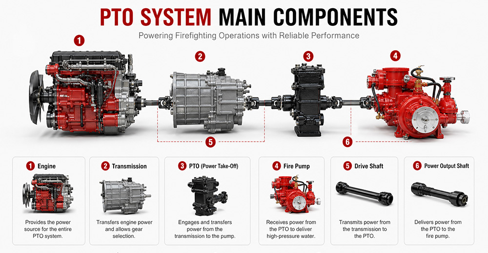
The fire pump is the final load of the PTO system, responsible for converting mechanical energy into water pressure energy.
Function: Receives rotational power from the PTO, drives the impeller to rotate, draws water in, and discharges it under high pressure.
Type: Centrifugal pump (single-stage, two-stage, or multi-stage).
Typical flow rate: 20 L/s – 180 L/s (1,200 – 6,000 L/min).
Typical pressure: 1.0 – 2.5 MPa (10 – 25 bar).
The PTO control system is the "command center" between the driver and the PTO system, responsible for engagement, disengagement, safety protection, and status indication.
Function: Controls PTO engagement and disengagement, monitors system status, and provides safety protection.
Operating location: Cab interior (primary control) and pump panel (auxiliary control).
Control methods: Manual cable, electric solenoid, pneumatic.
Specific control functions:
(1) PTO Engagement Control
The operator presses the PTO switch (electric solenoid/pneumatic) or pulls the lever (manual) in the cab. The control system sends a signal to engage the PTO's internal gears with the power source. After successful engagement is confirmed, an indicator light illuminates, allowing the operator to increase engine RPM.
(2) PTO Disengagement Control
The operator presses the switch again or resets the lever. The control system cuts the signal, and the PTO gears disengage. After disengagement is confirmed, the indicator light turns off.
| PTO Type | Installation Position | Power Source | Power Output | Typical Application |
| Sandwich PTO | Between engine and transmission | Engine flywheel | Full power (≥90%) | Fire pumpers, aerial trucks |
| Split-shaft PTO | Middle of chassis driveshaft | Transmission output shaft | Full power | Large vacuum trucks, airport fire trucks |
| Side-mounted PTO | Transmission side | Transmission gears | Partial power (lower) | Sprinkler trucks, small vacuum trucks |
Sandwich PTO
Advantages: Full power output (≥90%), supports "pumping while driving" (dual-function), high transmission efficiency, easy lubrication.
Disadvantages: Higher cost, complex installation, requires modification to the engine-transmission connection.
Split-shaft PTO
Advantages: Full power output, no additional space required, high reliability, good dynamic balance, can replace auxiliary engine to drive large pumps.
Disadvantages: Requires cutting the original driveshaft, installation position selection must consider driveshaft angle and length compensation.
Side-mounted PTO
Advantages: Low cost, simple installation, can draw power directly from the transmission side.
Disadvantages: Only partial power available, lower output torque, cannot drive high-power fire pumps, mainly used for low-speed, low-power equipment.
 for Fire Trucks")
The process follows a clear mechanical transmission chain:
Engine → PTO → Drive Shaft → Fire Pump → Impeller Rotation → Suction → Pressurization → Fire Monitor
| Factor | Role |
|---|---|
| Centrifugal pump characteristic | When impeller speed is constant, discharge pressure remains naturally stable |
| PTO rigid connection | No slippage or power loss, ensuring continuous stable power input |
| Pressure governor | Automatically detects flow changes and adjusts engine RPM to maintain set pressure |
| Relief valve | Automatically bypasses when pressure exceeds limit, preventing equipment damage |
① Pump speed is determined by engine RPM
Fire pump impeller speed = Engine RPM × PTO ratio. The PTO ratio is fixed (e.g., 1.75:1), so pump speed changes directly with engine RPM.
Calculation formula:
Engine RPM × PTO ratio = Pump speed (RPM)
② Physical relationship between pressure and speed
The pressure generated by a centrifugal pump is proportional to the square of the impeller speed. This physical law means that small changes in RPM cause significant pressure fluctuations.
Speed increases → Centrifugal force increases → Discharge pressure rises
Speed decreases → Centrifugal force decreases → Discharge pressure drops

1. PTO will not engage
Possible causes: Low air pressure (pneumatic type), faulty solenoid, damaged or stuck cable, interlock conditions not met (parking brake not applied, transmission not in neutral).
Solutions: Check air system pressure (must be ≥0.6 MPa); test solenoid; inspect cable; confirm parking brake is applied and transmission is in neutral.
2. PTO engages but pump does not work
Possible causes: PTO clutch failure, broken drive shaft or worn splines, damaged internal gears.
Solutions: Check PTO clutch engagement; inspect drive shaft for breakage or loose connections; disassemble and inspect internal gears.
3. PTO unusual noise
Possible causes: Poor gear meshing or wear, worn bearings, insufficient or degraded lubrication, PTO not fully disengaged.
Solutions: Check gear clearance and tooth wear; inspect bearings; replace with qualified lubricant; confirm PTO is fully disengaged.
4. PTO oil leakage
Possible causes: Worn or deteriorated seals, cracked housing, loose mounting bolts.
Solutions: Replace seals (O-rings, oil seals); inspect housing for cracks; tighten mounting bolts.
5. PTO overheating
Possible causes: Prolonged high-load operation, insufficient or degraded lubricating oil, cooling system failure.
Solutions: Reduce load or shut down for cooling; replace with qualified lubricant; inspect cooling lines.
6. PTO insufficient power
Possible causes: Improper PTO ratio selection, engine RPM set too low, clutch slippage.
Solutions: Confirm PTO ratio matches the fire pump; increase engine RPM to rated operating range; inspect clutch for slippage.
Q1. What does PTO stand for on a fire truck?
PTO stands for Power Take-Off. It is a mechanical system that transfers engine power from the truck's transmission to the fire pump. In simple terms, PTO allows the fire truck's engine to power the pumping system so it can deliver high-pressure water or foam for firefighting operations without needing a separate engine. It is a critical component in industrial and municipal fire trucks.
Q2. Why do fire trucks need a PTO?
Fire trucks need a PTO because it enables the vehicle's main engine to drive the fire pump efficiently. Without a PTO, the fire pump would require a separate engine, which increases cost, weight, and maintenance complexity. PTO systems provide a compact, reliable, and fuel-efficient way to ensure continuous water or foam supply during firefighting operations.
Q3. Can a fire truck operate without a PTO?
Most modern fire trucks cannot operate their pumping system without a PTO because the PTO is responsible for transferring engine power to the fire pump. However, some specialized fire vehicles may use an independent auxiliary engine to drive the pump. These designs are less common due to higher cost, increased maintenance, and lower efficiency compared to PTO-based systems.
Q4. What is the difference between PTO and a fire pump?
The PTO is a power transmission device, while the fire pump is a water or foam pumping system. The PTO delivers mechanical power from the engine to the pump, and the fire pump converts that power into hydraulic pressure to move water or foam. In short, PTO is the "power source connector," and the fire pump is the "firefighting output device."
Q5. How much power can a fire truck PTO provide?
The power output of a fire truck PTO depends on the vehicle design and transmission system. Typically, PTO systems can provide between 50 kW to over 300 kW of mechanical power. Heavy-duty industrial and airport fire trucks often use high-capacity PTO systems capable of supporting large-flow fire pumps and continuous high-pressure operations.
Q6. What are the different types of fire truck PTOs?
There are several types of fire truck PTO systems, including side-mounted PTO, rear-mounted PTO, split shaft PTO, and full power PTO. Side-mounted PTO is commonly used in standard fire trucks, while split shaft and full power PTO systems are used in industrial and airport fire trucks where higher power output and continuous operation are required.
Q7. How do you maintain a fire truck PTO?
PTO maintenance includes regular inspection of lubrication oil levels, checking for leaks, tightening mounting bolts, and ensuring proper alignment of the drive shaft. Operators should also test engagement and disengagement functions regularly. Preventive maintenance is essential to avoid overheating, mechanical wear, and unexpected failure during emergency operations.
Q8. What causes a fire truck PTO to fail?
Common causes of PTO failure include insufficient lubrication, worn gears, misalignment of the drive shaft, overheating, and improper operation by the driver. Electrical or hydraulic control system failures can also prevent PTO engagement. Regular maintenance and correct operating procedures significantly reduce the risk of PTO failure.
Q9. Which PTO is best for industrial fire trucks?
For industrial fire trucks, the best option is usually a split shaft PTO or full power PTO system. These systems can handle high power output, continuous operation, and large-capacity fire pumps. They are widely used in petrochemical plants, refineries, airports, and large industrial facilities where reliable and long-duration firefighting performance is required.
Q10. What should buyers consider when choosing a fire truck PTO?
Buyers should consider engine power compatibility, required fire pump flow rate, vehicle type, and working environment. It is also important to evaluate PTO durability, cooling performance, maintenance accessibility, and compatibility with the chassis. For export projects, compliance with international standards and local regulations should also be taken into account to ensure approval and operational reliability.
PTO (Power Take-Off) is the core system that transfers engine power to the fire pump — it determines whether the entire firefighting system can operate properly.
The fire truck power chain is: Engine → Transmission → PTO → Drive Shaft → Fire Pump → Fire Monitor. Any weak link in this chain affects final firefighting performance.
The primary function of the PTO is to provide stable, continuous mechanical power output, enabling the fire truck to deliver efficient water or foam supply without requiring a separate engine.
Different PTO types (Side-mounted, Rear-mounted, Split shaft, Full power) are suited to different fire truck classes. Industrial fire trucks typically prioritize high-power PTO systems.
PTO performance must match the fire pump flow rate and vehicle chassis, otherwise issues such as insufficient power, unstable pressure, or system overload may occur.
Regular PTO system maintenance (lubrication, tightening, alignment inspection) is key to ensuring reliable fire truck operation, especially in high-intensity industrial applications.
When purchasing industrial fire trucks, buyers should not focus solely on price. PTO power, stability, compatibility, and after-sales support are equally critical factors to evaluate.
For high-risk scenarios such as petrochemical plants, airports, and large industrial parks, Full Power PTO or Split Shaft PTO systems are recommended to ensure continuous operational capability.


Anda mungkin berminat dengan maklumat berikut
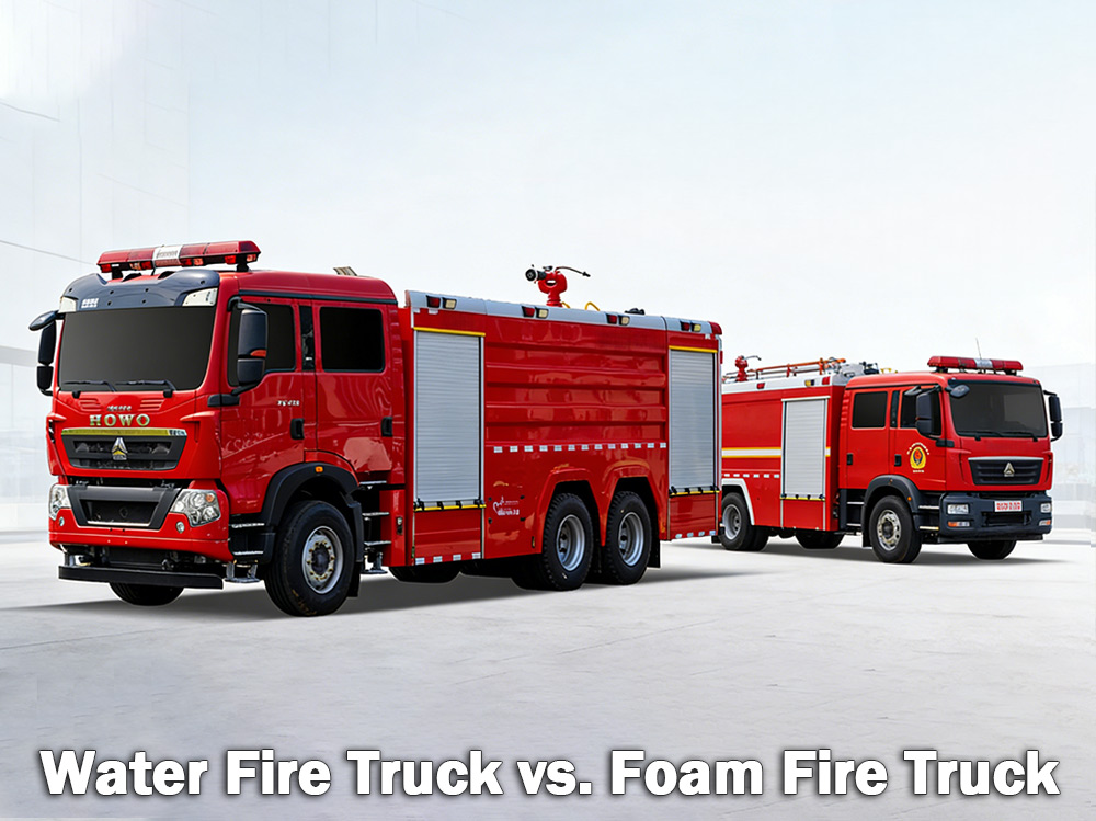
Trak bomba air memadamkan kebakaran biasa yang melibatkan kayu, kertas dan kain. Trak bomba buih memadamkan kebakaran cecair mudah terbakar seperti petrol dan minyak. Yang mana satu betul bergantung pada bahaya yang ada. A trak bomba air membawa tangki air yang besar dan bergantung pada pam tekanan tinggi untuk menyalurkan air melalui hos atau pistol dek. Ia merupakan jenis trak bomba yang paling biasa digunakan oleh jabatan bomba perbandaran dan tapak perindustrian di seluruh dunia. A trak bomba busa Sebaliknya, buih pemadam kebakaran direka khas untuk membawa dan menghantar buih pemadam kebakaran. Apabila air sahaja tidak dapat memadamkan api dengan berkesan — seperti dengan cecair mudah terbakar, bahan kimia atau kebakaran bahan api — buih adalah pilihan yang lebih baik. Buih berfungsi dengan membentuk selimut di atas api, memutuskan oksigen dan mencegah penyalaan semula. I. Apakah Trak Bomba Air? Trak bomba air adalah seperti apa yang didengarinya — sebuah kenderaan yang dilengkapi dengan tangki air yang besar, pam yang berkuasa dan hos atau monitor untuk menghantar air ke kebakaran. Tangki air biasanya memuatkan antara 500 dan 3,000 gelen (kira-kira 2,000 hingga 12,000 liter). Pam tersebut menarik air dari tangki atau dari sumber luaran seperti pili bomba, tasik atau kolam, kemudian menolaknya melalui hos di bawah tekanan tinggi. Di mana trak bomba air berfungsi dengan paling baik: Trak bomba air sesuai untuk Kebakaran Kelas A , yang melibatkan bahan mudah terbakar biasa: Kayu dan kayu balak Kertas dan kadbod Kain dan fabrik Getah dan plastik Rumput, semak, dan bahan hutan Jika kebakaran melibatkan bahan-bahan yang terbakar di rumah, gudang atau ladang, air biasanya akan memadamkannya. Had air: Air mempunyai satu kelemahan utama. Apabila disembur pada cecair yang terbakar seperti petrol, minyak atau bahan kimia, air akan tenggelam kerana ia lebih berat daripada bahan api ini. Bahan api tersebut terapung di atas dan terus terbakar. Dalam sesetengah kes, air juga boleh merebakkan api ke kawasan yang lebih luas. Itulah sebabnya air sahaja tidak berkesan untuk kebakaran cecair mudah terbakar. Spesifikasi pam bomba trak bomba air: Trak bomba air pemantau kebakaran spesifikasi: II. Apakah Trak Bomba Buih? Trak bomba busa ialah kenderaan khusus yang direka untuk mengangkut dan menghantar busa pemadam kebakaran. Ia membawa dua tangki berasingan — satu untuk air dan satu lagi untuk pekatan busa. Sistem perkadaran busa mencampurkan kedua-duanya pada nisbah tertentu, biasanya 1%, 3%, atau 6% pekatan busa kepada air. Campuran ini kemudiannya melalui muncung busa di mana udara ditambah, menghasilkan selimut busa yang mengembang dan stabil. Cara busa berfungsi: Buih tersebut membentuk lapisan di atas cecair atau bahan yang terbakar. Selimut ini: Memutuskan bekalan oksigen ke api Menyejukkan permukaan bahan api Menghalang wap mudah terbakar daripada keluar Menghalang api daripada menyala semula Di mana trak bomba busa berfungsi dengan paling baik: Trak bom...
Perincian
Trak bomba beroperasi melalui fungsi terselaras pelbagai sistem untuk mencapai bekalan air, penjanaan tekanan dan pemadaman kebakaran. Memahami prinsip-prinsip ini membantu kru bomba beroperasi dengan berkesan dalam situasi kecemasan. » Ⅰ. Bagaimana Trak Bomba Berfungsi: ▪ A. Sistem Pam: Jantung Pemadaman Kebakaran: Jantung mana-mana trak bomba ialah pamnya. Unit berkuasa tinggi ini menarik air dari tangki terbina dalam atau sumber luaran—seperti pili bomba, tasik atau kolam dan menyalurkannya melalui hos di bawah tekanan tinggi. Pam yang paling biasa digunakan ialah pam emparan, yang bergantung pada pendesak berputar untuk memberi tekanan dan menggerakkan air. Anggota bomba mengawal aliran air menggunakan beberapa tuil dan tolok pada panel pam. Mereka boleh melaraskan tekanan mengikut keperluan dan mengalirkan air ke pelbagai saluran hos secara serentak. Jenis Pam Ciri-ciri Aplikasi Terbaik Pam emparan satu peringkat Aliran tinggi, tekanan sederhana Pemadaman kebakaran perbandaran am Pam emparan dua peringkat Boleh bertukar antara isipadu dan tekanan Bangunan-bangunan tinggi, hos-hos panjang terbentang Pam berbilang peringkat Tekanan yang sangat tinggi Kemudahan perindustrian, sistem busa ▪ Parameter Pam Utama: › Kadar aliran: 1,200 - 6,000 liter seminit (bergantung pada model) › Tekanan maksimum: 1.0 - 2.5 MPa (10-25 bar) › Masa penyebuan: ≤30 saat ▪ B. Tangki Air dan Sistem Penyimpanan: › Kapasiti tangki: 500 - 1,500 gelen (kira-kira 2,000 hingga 6,000 liter), bergantung pada saiz dan jenis kenderaan › Bahan tangki: Keluli tahan karat tahan kakisan atau keluli karbon bersalut › Sekat dalaman: Pelbagai petak dengan reka bentuk anti-lonjakan untuk mengawal pergerakan air semasa tindak balas kecemasan › Masa pengisian: ≤3 minit melalui pili bomba atau pengekstrakan › Penunjuk paras air: Tolok visual di bahagian tangki; paparan kabin pilihan Tangki ini dibina daripada bahan tahan kakisan, biasanya keluli tahan karat atau keluli karbon bersalut, dengan plat sesekat dalaman yang mengawal lonjakan air semasa pemanduan tindak balas kecemasan. ▪ C. Sistem Hos dan Muncung Trak bomba membawa pelbagai hos dengan fungsi yang berbeza: › Hos serangan: diameter 1.5 - 2.5 inci — menyalurkan air terus ke sumber kebakaran › Hos bekalan: diameter 4 - 5 inci — mengangkut air dari pili air atau pam lain › Hos penggalak: diameter kecil pada gelendong — digunakan untuk kebakaran kecil seperti kebakaran rumput atau kenderaan Di hujung hos, muncung membolehkan anggota bomba mengawal aliran air, melaraskan tekanan, corak dan arah berdasarkan jenis kebakaran. ▪ D. Pemantau Kebakaran › Pemantau air: Menyalurkan aliran air isipadu tinggi untuk pemadaman kebakaran berskala besar; dikendalikan secara tetap atau dari jauh › Pemantau serbuk kering: Menyahcas serbuk kimia kering untuk kebakaran cecair, gas dan elektrik yang mudah terbakar › Monitor gabungan: Mampu mengeluarkan air dan serbuk kering; bertukar antara media mengikut keperluan ▪ E. Sistem Kawalan Enjin, Rangkaian K...
Perincian
Sebagai kilang trak Bomba Isuzu yang paling profesional, reka bentuk teras trak bomba busa air Isuzu NPR adalah untuk mengintegrasikan sistem pemadam api busa ke dalam trak bomba tangki air, membentuk peralatan pemadam api komposit yang boleh menyembur air dan busa. Ia boleh memadamkan kebakaran secara bebas; menghantar campuran air atau busa ke peralatan lain; dan sesuai untuk operasi di kawasan gersang dan kekurangan air. ★ Teknikal Spesifikasi Semua trak bomba daripada trak CS, 100% berdasarkan keperluan pelanggan Kapasiti Model enjin Air Buih Pam Kebakaran Pemantau Kebakaran 2,500L ISUZU 4HK1 / 19 0HP 2,500L 500L Pam Kebakaran CB10/40 PL8/32 Trak casis kabin trak bomba ISUZU rasmi 2026 Lukisan casis trak bomba asal 2026 Barang Butiran Reka Bentuk Trak Bomba Isuzu Teras Reka Bentuk Mengintegrasikan sistem pemadam buih ke dalam trak bomba tangki air, membentuk kenderaan pemadam kebakaran berkemampuan dua yang mampu mengeluarkan air dan buih. Ciri-ciri termasuk: • Penindasan kebakaran bebas • Bekalan air atau campuran buih ke peralatan lain • Sesuai untuk kawasan gersang atau kekurangan air, membolehkan penggunaan pelbagai fungsi Konsep Reka Bentuk Keseluruhan Direka untuk memenuhi keperluan pemadaman kebakaran di bengkel dan kawasan sekitarnya, dengan keupayaan yang dipertingkatkan untuk kebakaran minyak, elektrik dan bahan pepejal; kenderaan ini terdiri daripada casis dan peralatan badan khusus, yang menekankan kebolehpercayaan, pelbagai fungsi dan kemudahan pengendalian. Pemilihan Casis • Menggunakan casis jenis-II tugas sederhana atau berat yang terbukti • Pacuan semua roda disyorkan untuk meningkatkan mobiliti dan cengkaman di medan yang kompleks REKA BENTUK BARU 2026 ISUZU 700P Trak Bomba Air Komponen Sistem Teras & Reka Bentuk Perkara Utama 1. Tangki Air & Tangki Cecair Buih • Bahan: Keluli tahan karat, tahan kakisan • Kapasiti yang disyorkan: Tangki air 3000–5000L, tangki cecair busa 300–600L • Pengoptimuman struktur: Sekat dalaman memisahkan ruang air dan buih, boleh ditukar melalui port penyambung kepada mod tangki air tunggal, membolehkan penggunaan pelbagai guna 2. Sistem Pengagihan Buih • Menggunakan pengatur tekanan seimbang (komponen teras) untuk mencampurkan air dan pekatan busa dengan tepat pada nisbah 3% atau 6% • Output stabil tidak terjejas oleh turun naik aliran atau tekanan, sesuai untuk pengendali bukan pakar • Dilengkapi dengan saluran masuk sedutan buih luaran untuk pengisian semula di lokasi 3. Sistem Pelepasan • Pam bomba: Pam emparan berbilang peringkat yang cekap tinggi dan menjimatkan tenaga, kadar aliran ≥ 4 0 L/S • Pemantau kebakaran: Pemantau dwi-guna air/buih kawalan jauh, jarak ≥50 meter, sudut boleh laras • Menyokong sambungan kepada hos bomba dan muncung busa untuk operasi fleksibel REKA BENTUK BAHARU 2026 ISUZU NPR Foam Fire Truck Senario & Kelebihan Aplikasi Kebakaran tumpahan minyak bengkel Amat sesuai; buih memadamkan api dengan cepat melalui pengasingan oksigen Kebakaran peralatan elektrik awal Buih atau...
Perincian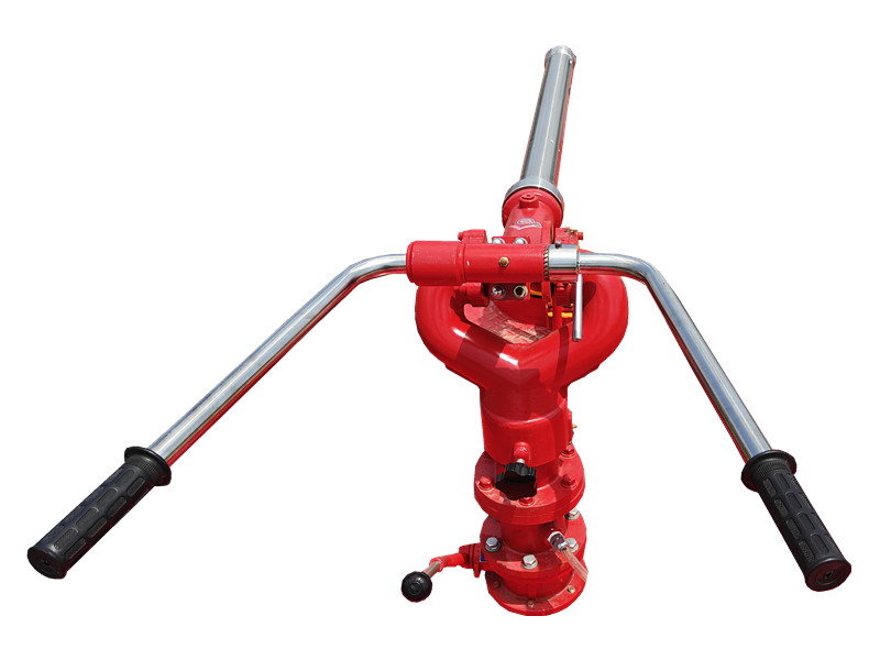
PF5-15 monitor serbuk kering tetap Menggunakan serbuk kering sebagai medium dan bergantung pada tapak tetap untuk semburan yang stabil. Ia sesuai untuk kawasan kimia dan gudang, dan boleh menutup permukaan yang terbakar dengan cepat pada peringkat awal kebakaran, meningkatkan kecekapan pemadaman. Yang Monitor serbuk kering tetap PF5-15 mempunyai struktur yang teguh, mudah dikendalikan, dan boleh dihubungkan dengan sistem kawalan automatik untuk pengaktifan jarak jauh dan penyemburan yang tepat. » Ⅰ. Monitor serbuk kering tetap PF5-15 struktur: Ciri-ciri monitor serbuk kering tetap PF5-15: ● Berfungsi sepenuhnya; ● Struktur yang ringkas dan baharu; ● Prestasi yang stabil dan penyelenggaraan yang mudah; ● Tekanan masuk yang rendah; ● Dilengkapi dengan injap longkang automatik dengan fungsi penguncian mendatar dan menegak; ● Bahan: Aloi aluminium tuangan jitu; ● Kepala meriam: Aloi aluminium. » Ⅱ. Meriam Buih PL24 spesifikasi: Model Aliran ( kg /s ) Julat ( m ) Tekanan kerja yang dinilai ( Mpa ) Putaran padang ( ° ) Putaran mendatar ( ° ) P×L×T ( mm ) Berat ( Kg ) PF5-15/40 40 ≥42 0.80 -45 ~ +70 0 ~ 360 980x340x550 28.5 » Ⅲ. Aplikasi Produk: Trak bomba dengan monitor serbuk kering tetap PF5-15 Ujian monitor serbuk kering tetap PF5-15 Monitor serbuk kering tetap PF5-15 mempunyai jarak semburan yang jauh dan liputan yang luas, dan boleh membentuk penghalang pemadam api serbuk kering dengan cepat. Ia sesuai untuk lokasi tetap seperti loji kimia, depot minyak dan kawasan penyimpanan, menyediakan keupayaan pemadaman api yang berterusan dan stabil untuk kawasan yang luas.
Perincian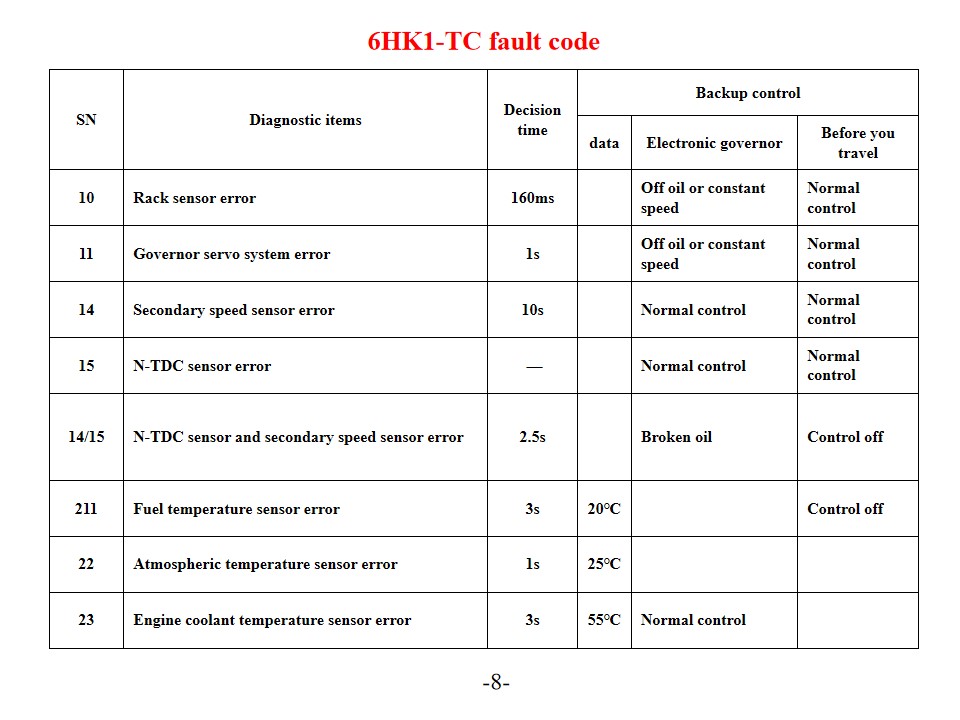
Trak bomba Isuzu 6HK1-TC , juga dinamakan Kenderaan bomba penyelamat Isuzu , Diagnosis dan Penyelesaian Kod Ralat Enjin. Enjin Isuzu 6HK1-TC menggunakan sistem kawalan elektronik pam suntikan bahan api TICS yang canggih, dan ECU (Unit Kawalan Enjin) mempunyai ciri diagnosis kendiri. Apabila sistem mengesan kerosakan, lampu amaran "CEK ENJIN" akan menyala dan kod kerosakan yang sepadan akan disimpan. Memahami tafsiran dan penyelesaian untuk kod ralat ini dapat meningkatkan kecekapan penyelenggaraan enjin dengan berkesan. Kod Ralat dan Penyelesaian Biasa Kod Masalah Siri-P P0101 (Litar Sensor Aliran Udara Jisim Rendah) Periksa sensor suhu penyejuk enjin dan pendawaiannya. Sahkan voltan bekalan kuasa sensor dan sambungan pembumian. Gantikan ECU atau sensor jika perlu. P0102 (Litar Sensor Aliran Udara Jisim Tinggi) Periksa kualiti bahan api dan keadaan penapis. Bersihkan sistem bahan api. Periksa pengatur tekanan bahan api, pam bahan api dan litar penyuntik. P0103 (Sensor Aliran Udara Jisim Litar A Tinggi) Periksa litar isyarat sensor untuk litar pintas. Uji status operasi sensor. Gantikan sensor atau ECU jika perlu. Kod Masalah Digital 10 (Ralat Sensor Rak) Periksa sensor rak dan pendawaiannya. Sahkan penghantaran isyarat normal. 11 (Ralat Sistem Servo Gabenor Kelajuan) Periksa status operasi sistem servo pengawal kelajuan. Uji sambungan litar yang berkaitan. 14 (Ralat Sensor Kelajuan Bantu) Periksa kedudukan pemasangan sensor kelajuan tambahan. Uji output isyarat sensor. 15 (Ralat Sensor N-TDC) Periksa sambungan sensor N-TDC Sahkan ketepatan isyarat Penyelenggaraan sistem dan langkah pencegahan SN Item diagnostik Masa keputusan Kawalan sandaran data Gabenor elektronik Sebelum anda melancong 10 Ralat sensor rak 160ms Dimatikan minyak atau kelajuan malar Kawalan biasa 11 Ralat sistem servo gabenor 1s Dimatikan minyak atau kelajuan malar Kawalan biasa 14 Ralat sensor kelajuan sekunder 10-an Kawalan biasa Kawalan biasa 15 Ralat sensor N-TDC — Kawalan biasa Kawalan biasa 14/15 Sensor N-TDC dan ralat sensor kelajuan sekunder 2.5s Minyak pecah Kawalan dimatikan 211 Ralat sensor suhu bahan api 3s 20℃ Kawalan dimatikan 22 Ralat sensor suhu atmosfera 1s 25℃ 23 Ralat sensor suhu penyejuk enjin 3s 55℃ Kawalan biasa Penyambung No. Terminal Isyarat Diameter/kotor dawai (Abah-abah pam suntikan) SWP 8-terminal Hitam 1 Voltan pemacu penggerak gabenor - 1 RM2 2 Litar Gabenor GND-1 Dengan 1.2 3 Kedudukan rak sasaran - 1 U1 2 4 Voltan kedudukan rak G/1.2 5 Litar gabenor 5V-1 Y/1.2 6 Sensor N sandaran (GND) BR/1.2 7 Sensor N sandaran (SIG) 0/1.2 8 Tarik ke bawah B/1.2 SWP6- terminal Hitam g Voltan pemacu penggerak gabenor - 2 R/1.2 10 Kedudukan rak sasaran - 2 L/1.2 11 Litar Gabenor GND-2 Dengan 1.2 12 Litar Gabenor SIG-GND BR/1.2 13 Litar gabenor 5V-2 Y/1.2 SWP 3- terminal Hitam 14 Rumah Limp W1.2 15 Sub-gegelung (Tidak digunakan) OLEH/1.2 Penyelenggaraan berkala Tukar minyak enjin mengikut jadual (berdasarkan keperluan perbatuan dan suhu) Gantikan tiga penapis (penap...
Perincian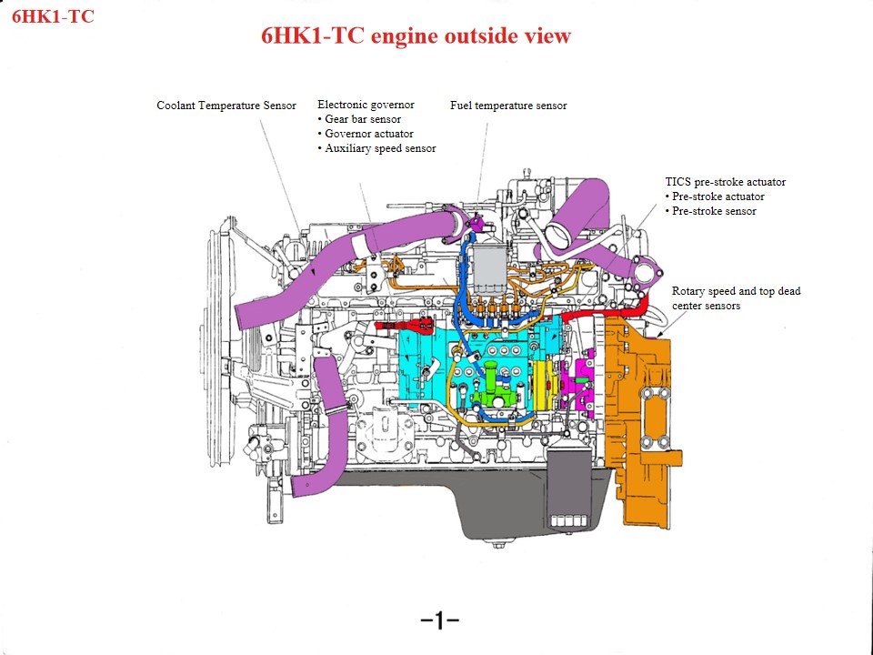
Kenderaan Penyelamat Bomba Isuzu 6HK1 , juga dinamakan Trak perkhidmatan bomba Isuzu , Jika enjin trak bomba penyelamat Isuzu terlalu panas, bahagian berikut perlu diperiksa terlebih dahulu: 1. Sistem penyejukan: Masalah seperti kipas yang rosak, radiator tersumbat, termostat yang rosak atau penyejuk yang tidak mencukupi semuanya boleh menyumbang kepada enjin yang terlalu panas. 2. Kualiti dan kuantiti minyak: Kualiti minyak yang buruk atau minyak yang tidak mencukupi juga boleh menyebabkan enjin terlalu panas. 3. Kegagalan mekanikal seperti silinder meletup, retakan pelapik silinder atau retakan pelapik silinder juga boleh menyebabkan fenomena ini. Sebagai rangkaian kuasa diesel tugas berat, enjin Isuzu 6HK1 memerlukan pematuhan ketat terhadap spesifikasi teknikal untuk penyelenggaraan. Perkara utama adalah seperti berikut: 1. Pemahaman Struktur dan Spesifikasi Pembongkaran dan Pemasangan Mekanisme Rod Penghubung Aci Engkol Pelapik silinder mempunyai reka bentuk yang longgar, memerlukan alat khas untuk mengelakkannya daripada jatuh semasa pembongkaran dan pemasangan. Jarak pelepasan standard ialah 0.122–0.156mm. Diameter luar omboh mempunyai toleransi yang ketat (114.894–114.909mm). Semasa pemasangan, beri perhatian kepada arah pembukaan gelang omboh dan pelarasan "tiga kelegaan" (kelegaan hujung, kelegaan sisi dan kelegaan belakang). Kotak engkol bawah ialah struktur satu bahagian dan mesti diangkat semasa penyelenggaraan untuk mengelakkan ubah bentuk. Penjajaran Sistem Pemasaan Semasa pemasangan kotak gear, jajarkan tanda gear aci engkol dan gear idler. Tanda aci sesondol B mesti rata dengan permukaan kepala silinder. Enjin hendaklah berada pada pusat mati atas mampatan pada silinder pertama. Semasa memasang pam suntikan bahan api, jajarkan penunjuk masa dengan titik S pada penyambung, dan jajarkan tanda pemaju suntikan dengan penunjuk badan pam. • Motor DC linear menolak gegelung ke atas dan ke bawah di bawah isyarat output unit kawalan. • Rod penyambung yang dipasang pada pemasangan gegelung menghantar gerakan ke atas dan ke bawah gegelung ke blok penyambung, dan blok penyambung dipasang di hujung rak. Di bawah tolakan blok penyambung, rak bergerak ke kiri dan kanan untuk mengubah jumlah bahan api yang disuntik. Apabila pemasangan gegelung bergerak ke atas, pautan menolak rak untuk meningkatkan arah minyak; sebaliknya, apabila pemasangan gegelung turun, rak bergerak ke arah pengurangan minyak, dan fungsi lajur adalah untuk menukar gerakan menegak kepada ketinggian rak. • Blok kuprum dipasang pada bahagian atas blok penyambung untuk membentuk sensor rak. Sensor rak mengesan lejang rak dan menyalurkan nilai ini kembali ke unit kawalan supaya lejang rak sebenar dan lejang rak sasaran dapat dibandingkan secara berterusan sehingga perbezaan antara keduanya menghampiri sifar. Proses ini sangat penting untuk mengawal ketepatan dan tindak balas. 2. Titik Penyelenggaraan Sistem Utama Sistem Pelinciran dan Penyejukan Selang penukaran minyak: Minyak mi...
Perincian
Sila baca selanjutnya, terus berhubung, langgan, dan kami mengalu-alukan anda untuk berkongsi pendapat anda.

 Rangkaian IPv6 disokong

 Melayu
 English
 français
 Deutsch
 русский
 italiano
 español
 português
 Nederlands
 العربية
 日本語
日本語 한국의
한국의 Türkçe
 ไทย
ไทย Tiếng Việt
 Indonesia
  中文
中文 қазақ
қазақ Filipino
 မြန်မာ
 српски