Tinggalkan Pesan
Jika anda berminat dengan produk kami dan ingin mengetahui lebih lanjut, sila tinggalkan pesanan di sini, kami akan membalas anda secepat mungkin.

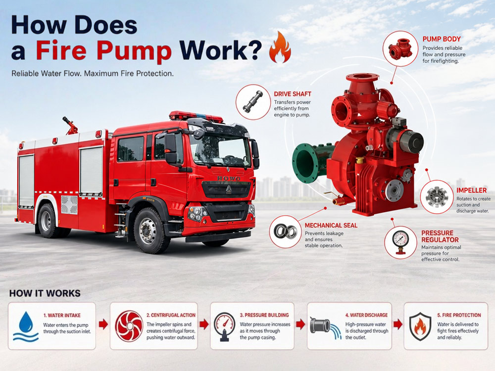
Bagaimanakah Pam Bomba Berfungsi? Prinsip Kerja Pam Lori Bomba Diterangkan
Pam bomba kebakaran ialah nadi utama sistem penghantaran air setiap trak bomba. Sama ada bertindak balas terhadap kebakaran struktur, kecemasan industri, insiden lapangan terbang, atau operasi kawasan liar, pam bombapada sebuah trak bomba bertanggungjawab menghantar air bertekanan tinggi ke hos, monitor kebakaran, dan sistem buih.Reka bentuk pendesak emparnya dan sistem dipacu PTO memastikan tekanan stabil serta kadar aliran tinggi, secara langsung meningkatkan keberkesanan pemadaman kebakaran lebih daripada 40%, sambil mengurangkan masa tindak balas sebanyak 3 kali ganda. Ia boleh dipanggil penjaga tidak kelihatan bagi operasi pemadaman kebakaran dan asas teknikal tindak balas kecemasan moden.
Ketahui cara pam bomba berfungsi, termasuk prinsip kerja, komponen utama, proses aliran air, penjanaan tekanan, dan aplikasi. Temui cara pam trak bomba membekalkan bekalan air yang boleh dipercayai untuk pemadaman kebakaran serta cara memilih pam yang sesuai untuk kenderaan pemadam kebakaran anda.Mari pelajarinya hari ini.
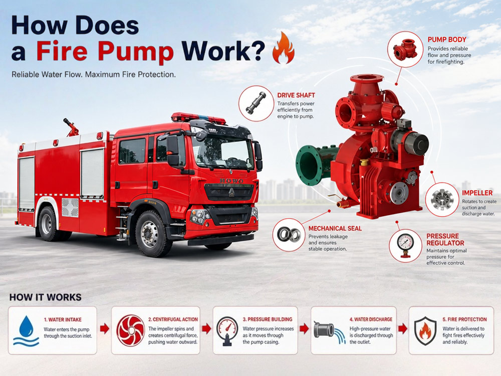
1. Pendesak: Komponen berputar yang menarik masuk air dan melontarkannya keluar melalui daya empar. Biasanya diperbuat daripada gangsa, keluli tahan karat, atau besi tuang.
2. Selongsong pam: Perumah yang mengandungi pendesak dan mengarahkan aliran air. Direka untuk menukar halaju kepada tekanan.
3. Pengambilan Kuasa (PTO): Sambungan mekanikal yang memindahkan kuasa enjin daripada transmisi trak ke pam bomba.
1. Kuasa dipindahkan daripada enjin melalui PTO
Enjin trak memacu PTO, yang bersambung dengan aci pam. Apabila pengendali mengaktifkan PTO, kuasa enjin dialihkan untuk memutarkan pendesak pam pada kelajuan tinggi.
2. Pendesak mula berputar
Pendesak berputar pada 1,500–2,500 RPM, menarik air masuk ke dalam pam melalui salur masuk sedutan. Bilah pendesak yang berputar menghasilkan zon tekanan rendah di bahagian tengah, menarik air masuk daripada tangki terbina dalam, pili bomba, atau sumber air semula jadi.
3. Daya empar meningkatkan tekanan air
Apabila pendesak berputar, ia melontarkan air keluar melalui daya empar. Halaju air meningkat apabila ia bergerak dari tengah ke tepi luar pendesak. Selongsong pam kemudian menukarkan halaju ini kepada tekanan, memaksa air bertekanan tinggi keluar melalui salur keluar pelepasan.
4. Air bertekanan tinggi keluar melalui salur keluar pelepasan
Air bertekanan (biasanya 0.8–1.2 MPa) keluar melalui salur keluar pelepasan dan dihantar ke hos kebakaran, monitor kebakaran, atau sistem perkadaran buih untuk operasi pemadaman kebakaran.
Pam bomba boleh menarik air daripada tiga sumber:
Tangki air terbina dalam: Sumber air utama untuk serangan awal. Kapasiti biasa: 2,000–12,000 liter. Membekalkan air serta-merta apabila tiba di lokasi.
Pili bomba: Disambungkan melalui hos bekalan. Membekalkan bekalan air berterusan untuk operasi lanjutan. Tekanan daripada pili bomba membantu pam mengekalkan aliran.
Sumber air semula jadi (penyedutan): Tasik, sungai, kolam, atau kolam renang. Pam menggunakan sistem penyebuan untuk mengeluarkan udara daripada hos sedutan sebelum penyedutan. Daya angkat teori maksimum pada paras laut: kira-kira 10 meter (33 kaki). Kedalaman penyedutan berkesan: biasanya 7–8 meter.
Proses penyedutan:
Sambungkan hos sedutan tegar ke salur masuk pam
Tenggelamkan penapis sekurang-kurangnya 2-3 kaki di bawah permukaan air
Aktifkan penyebuan untuk mengeluarkan udara daripada hos dan pam
Vakum terbina, tekanan atmosfera menolak air ke atas
Air memenuhi pam, kemudian pam empar memberi tekanan kepadanya
Salur masuk sedutan: Tempat air memasuki pam. Saiz biasa: DN100–DN150. Dilengkapi dengan penapis untuk menghalang serpihan daripada masuk.
Saluran keluar pelepasan:Tempat air bertekanan keluar. Saiz biasa: DN65–DN80 (saluran keluar standard). Dilengkapi dengan injap untuk mengawal aliran ke hos atau pemantau. Pelbagai saluran keluar membolehkan penggunaan serentak.
Pendesak:Komponen berputar yang menghasilkan aliran air. Menukar tenaga mekanikal kepada tenaga kinetik. Biasanya diperbuat daripada gangsa (tahan kakisan), keluli tahan karat (tahan lasak, jangka hayat panjang), atau besi tuang (kos efektif untuk aplikasi standard).
Selongsong pam:Perumah yang mengarahkan aliran air. Direka untuk menukar halaju kepada tekanan. Reka bentuk biasa: selongsong volut (bentuk lingkaran untuk aliran lancar) dan selongsong peresap (untuk kecekapan lebih tinggi).
Sistem penyebuan:Mengeluarkan udara daripada pam dan hos sedutan sebelum proses penyedutan air. Jenis termasuk:
Penyebuan vakum:Reka bentuk ram berputar atau omboh. Cepat dan cekap. Paling biasa digunakan dalam trak bomba moden.
Penyebuan ekzos:Menggunakan ekzos enjin untuk menghasilkan vakum. Ringkas tetapi kurang berkesan.
Penyebuan elektrik:Digerakkan oleh motor. Boleh melakukan penyebuan tanpa putaran pam. Melindungi pengedap mekanikal daripada kerosakan akibat operasi kering.
Injap pelepas tekanan:Menghalang tekanan berlebihan. Terbuka apabila tekanan melebihi had yang ditetapkan. Melindungi hos, pam dan anggota bomba.
Pengawal tekanan:Mengekalkan tekanan yang ditetapkan secara automatik. Melaraskan RPM enjin untuk mengimbangi perubahan aliran. Mengurangkan beban kerja pengendali. Tersedia dalam mod tekanan (mengekalkan tekanan pratetap) dan mod RPM (mengekalkan kelajuan enjin pratetap).
PTO (Pengambilan Kuasa):Sambungan antara enjin dan pam. Memindahkan kuasa enjin untuk menggerakkan pam. Trak bomba biasanya menggunakan PTO sandwic (dipasang antara enjin dan transmisi) untuk output kuasa penuh.
| Jenis Pam | Kelebihan | Aplikasi Biasa |
|---|---|---|
| Pam empar satu peringkat | Aliran tinggi, reka bentuk ringkas, kos efektif | Trak bomba perbandaran |
| Pam bomba dua peringkat | Tekanan lebih tinggi, mod boleh ditukar | Pemadaman kebakaran bangunan tinggi, susunan hos panjang |
| Pam bomba pertengahan kapal | Keseimbangan lebih baik, operasi stabil | Jentera bomba standard |
| Pam bomba dipasang belakang | Penyelenggaraan lebih mudah, penyejukan lebih baik | Trak lapangan terbang dan industri |
| Item Perbandingan | Pam Bomba | Pam Air Standard |
|---|---|---|
| Tekanan kerja | Tinggi (0.8–2.5 MPa) | Lebih rendah (0.2–0.6 MPa) |
| Kadar aliran | Tinggi (1,200–6,000 L/min) | Sederhana (500–2,000 L/min) |
| Operasi berterusan | Ya (direka untuk penggunaan berpanjangan) | Bergantung pada model |
| Digerakkan PTO | Ya | Biasanya tidak |
| Pematuhan standard pemadaman kebakaran | Ya (diperakui NFPA, EN, GB) | Tidak |
| Kawasan aplikasi | Pemadaman kebakaran dan penyelamatan | Bekalan air industri, pertanian, domestik |
| Aplikasi | Pam Disyorkan | Sebab |
|---|---|---|
| Pemadaman kebakaran perbandaran | Satu peringkat (1,200–3,000 L/min) | Kos efektif, mencukupi untuk kebanyakan kebakaran |
| Bangunan bertingkat tinggi | Dua peringkat (2,000–4,000 L/min) | Tekanan lebih tinggi untuk pengangkatan menegak |
| Loji petrokimia | Dua peringkat (3,000–6,000 L/min) | Aliran tinggi, tekanan untuk kebakaran industri |
| Penyelamatan kemalangan pesawat di lapangan terbang | Pemasangan belakang (4,000–6,000 L/min) | Aliran tinggi, penyelenggaraan lebih mudah |
| Pemadaman kebakaran kawasan liar | Satu peringkat (1,000–2,000 L/min) | Ringan, mudah alih |
Pam kebakaran membina tekanan melalui daya empar. Apabila pendesak berputar, ia menarik air ke bahagian tengah dan melontarkannya keluar pada kelajuan tinggi. Perumah pam menukar air berkelajuan tinggi ini menjadi tekanan dengan memperlahankannya.
Faktor yang mempengaruhi tekanan:
Kelajuan pendesak:Putaran lebih pantas = tekanan lebih tinggi. Kelajuan pendesak berkadar terus dengan RPM enjin.
RPM enjin:Kelajuan enjin lebih tinggi = pendesak lebih pantas = tekanan lebih tinggi. Operator mengawal tekanan dengan melaraskan pendikit enjin atau menggunakan pengawal tekanan.
Reka bentuk pam:Pam dua peringkat boleh mencapai tekanan lebih tinggi berbanding pam satu peringkat dengan menggunakan dua pendesak secara bersiri.
Diameter paip:Diameter lebih kecil = tekanan lebih tinggi tetapi aliran lebih rendah. Diameter lebih besar = tekanan lebih rendah tetapi aliran lebih tinggi. Operator mesti mengimbangi tekanan dan aliran berdasarkan tugas pemadaman kebakaran.
Sumber air:Bekalan air yang mencukupi adalah penting untuk mengekalkan tekanan. Bekalan yang tidak mencukupi menyebabkan tekanan menurun.
1. Pam tidak dapat dipam mula
Punca yang mungkin: Kebocoran udara dalam hos sedutan, penapis tersumbat, pemula pam tidak berfungsi.
Penyelesaian: Periksa dan ketatkan semua sambungan hos sedutan; bersihkan penapis; periksa sistem pemula (pam vakum atau pemula elektrik) dan baiki jika perlu.
2. Tekanan air rendah
Punca yang mungkin: Penapis tersumbat, RPM enjin tidak mencukupi, pendesak haus, udara dalam sistem.
Penyelesaian: Bersihkan penapis; tingkatkan kelajuan enjin; periksa kehausan pendesak dan gantikan jika perlu; periksa kebocoran udara dan lakukan pemula pam semula.
3. Kavitasi
Pembentukan: Kavitasi berlaku apabila pam tidak menerima air yang mencukupi. Pendesak berputar dalam campuran air dan gelembung wap. Apabila gelembung ini runtuh, ia menghasilkan gelombang kejutan yang merosakkan pendesak dan menyebabkan turun naik tekanan yang teruk.
Cara mengelakkan: Jangan sekali-kali menjalankan pam lebih laju daripada kadar bekalan air yang boleh dihantar; pantau tekanan masukan; kurangkan kelajuan pam jika vakum terlalu tinggi; pastikan penapis tidak tersumbat.
4. Kebocoran air
Perkara pemeriksaan: Periksa semua pengedap dan gasket; periksa keretakan pada perumah pam; pastikan injap saliran ditutup; gantikan pengedap yang haus dengan segera.
5. Terlalu panas
Punca: Pam beroperasi tanpa air, penyejukan tidak mencukupi, operasi berpanjangan tanpa aliran air.
Petua penyelenggaraan: Jangan sekali-kali menjalankan pam tanpa air; pastikan saluran penyejukan tidak tersumbat; biarkan pam sejuk antara operasi; periksa injap pelepasan haba secara berkala.
» VIII. Kajian kes sebenar: Naik taraf pam jabatan bomba perbandaran
Latar belakang:
Sebuah jabatan bomba perbandaran dengan armada trak bomba yang semakin berusia perlu menaik taraf sistem pam pada tiga enjin barisan hadapan. Pam sedia ada menghadapi kesukaran mengekalkan tekanan semasa operasi pemadaman kebakaran bangunan tinggi dan kerap memerlukan pembaikan.
Cabaran:
Tekanan tidak stabil pada ketinggian melebihi 50 meter
Penyedutan perlahan dari sumber air semula jadi (masa pemula pam >45 saat)
Kadar aliran rendah pada tekanan tinggi
Kegagalan pengedap yang kerap dan kehausan pendesak
Penyelesaian:
Pam kebakaran CB10/60 (60 L/s @ 1.0 MPa)
Pemula vakum elektrik (meningkatkan kelajuan pemula pam)
Pengawal tekanan automatik (mengekalkan tekanan stabil)
Meterai dan galas pam yang dinaik taraf
Hos sedutan baru dengan penapis lebih besar
Keputusan:
| Metrik | Sebelum | Selepas |
|---|---|---|
| Tekanan pada ketinggian 50m | 0.6 MPa | 0.9 MPa |
| Masa pemadanan | 45 saat | 18 saat |
| Kadar aliran pada tekanan penuh | 40 L/s | 55 L/s |
| Penggantian meterai setiap tahun | 4 | 0 |
Tekanan meningkat sebanyak 25%, masa pemadanan dikurangkan sebanyak 35%, kecekapan pemadaman kebakaran meningkat dengan ketara, dan kos penyelenggaraan turun sebanyak 60%. Jabatan melaporkan masa tindak balas lebih pantas dan pam lebih boleh dipercayai semasa kebakaran berskala besar.
1. Tentukan kadar aliran yang diperlukan
| Aplikasi | Kadar Aliran yang Disyorkan |
|---|---|
| Pemadaman kebakaran perbandaran | 30–60 L/s |
| Taman perindustrian | 60–100 L/s |
| Penyelamatan kemalangan lapangan terbang | 100+ L/s |
| Pemadaman kebakaran hutan | 20–40 L/s |
| Bangunan tinggi | 40–80 L/s |
2. Tentukan tekanan yang diperlukan
| Aplikasi | Tekanan Disyorkan |
|---|---|
| Pemadaman kebakaran perbandaran | 0.8–1.0 MPa |
| Taman perindustrian | 1.0–1.2 MPa |
| Loji petrokimia | 1.2–1.4 MPa |
| Penyelamat kemalangan lapangan terbang | 1.0–1.2 MPa |
| Bangunan bertingkat tinggi | 1.5–2.5 MPa |
3. Pertimbangkan sumber air
Bekalan pili bomba:Pam satu peringkat adalah mencukupi. Tiada penyebuan diperlukan.
Tangki atas kenderaan:Satu peringkat atau dua peringkat. Penyebuan diperlukan untuk penyedutan air.
Air semula jadi (penyedutan):Memerlukan penyebar vakum. Dua peringkat untuk angkatan tinggi.
4. Saiz dan konfigurasi trak bomba
| Casis | Pam Disyorkan |
|---|---|
| 4×2 | Satu peringkat, 1,200–2,000 L/min |
| 4×4 | Satu peringkat, 2,000–3,000 L/min |
| 6×4 | Dua peringkat, 3,000–4,500 L/min |
| 8×4 | Dua peringkat, 4,000–6,000 L/min |
S: Apakah itu pam bomba?
J: Pam bomba ialah pam empar yang digerakkan oleh enjin trak melalui sistem PTO. Ia menarik air daripada tangki atas kenderaan, pili bomba, atau sumber air semula jadi, meningkatkan tekanan air dengan memutarkan pendesak, dan menghantar air bertekanan tinggi ke hos atau monitor kebakaran untuk operasi memadam kebakaran.
S: Bagaimanakah pam bomba meningkatkan tekanan air?
J: Pendesak berputar pada kelajuan tinggi (1,500–2,500 RPM), menarik air ke bahagian tengah dan mencampakkannya ke luar oleh daya empar. Perumah pam menukar air berkelajuan tinggi ini kepada tekanan dengan memperlahankannya. Kelajuan pendesak yang lebih tinggi = tekanan yang lebih tinggi.
S: Adakah pam bomba sama seperti pam air standard?
J: Tidak. Pam bomba direka untuk tekanan lebih tinggi (0.8–2.5 MPa), kadar aliran lebih tinggi (1,200–6,000 L/min), dan operasi kecemasan berterusan. Pam air standard beroperasi pada tekanan lebih rendah dan tidak direka untuk pemadaman kebakaran atau sistem dipacu PTO.
S: Apakah yang menggerakkan pam trak bomba?
J: Enjin trak bomba menggerakkan pam bomba melalui sistem Power Take-Off (PTO). Apabila pengendali mengaktifkan PTO, kuasa enjin dialihkan untuk memutarkan pendesak pam. Tiada enjin berasingan diperlukan.
S: Mengapakah pam bomba memerlukan penyebuan?
J: Penyebuan mengeluarkan udara daripada pam dan hos sedutan sebelum menyedut air dari tasik, sungai, atau kolam. Pam empar tidak boleh mengalirkan air jika terdapat udara dalam sistem. Penyebuan menghasilkan vakum, membolehkan tekanan atmosfera menolak air masuk ke dalam pam.
S: Apakah perbezaan antara pam bomba satu peringkat dan dua peringkat?
A: Pam satu peringkat mempunyai satu pendesak dan menyediakan kadar aliran tinggi pada tekanan sederhana. Pam dua peringkat mempunyai dua pendesak secara bersiri dan boleh memberikan tekanan lebih tinggi. Pam dua peringkat boleh bertukar antara mod isipadu (aliran tinggi) dan mod tekanan (tekanan tinggi).
Q: Bolehkah pam kebakaran menarik air dari sungai?
A: Ya. Pam kebakaran boleh menarik air dari sungai, tasik, kolam, dan kolam renang melalui proses yang dipanggil penyedutan terus. Pemula mengeluarkan udara daripada hos sedutan dan pam, lalu mewujudkan vakum. Tekanan atmosfera menolak air naik ke dalam pam. Ketinggian angkat praktikal maksimum: kira-kira 7–8 meter.
Q: Apakah yang menyebabkan kavitasi pam kebakaran?
A: Kavitasi berlaku apabila pam tidak menerima air yang mencukupi. Pendesak berputar dalam campuran air dan gelembung wap. Apabila gelembung ini runtuh, ia menghasilkan gelombang kejutan yang merosakkan pendesak. Kavitasi disebabkan oleh menjalankan pam lebih laju daripada kemampuan bekalan air, penapis yang tersumbat, atau angkatan sedutan yang berlebihan.
Q: Berapa kerapkah pam kebakaran perlu diservis?
A: Pemeriksaan harian (bunyi, getaran, kebocoran), ujian mingguan (pemula, pengawal tekanan), pemeriksaan bulanan (pendesak, galas, injap pelepas), ujian aliran penuh tahunan dan ujian tekanan hidrostatik. Penyelenggaraan berkala mencegah kegagalan tidak dijangka semasa kecemasan.
Q: Bagaimanakah saya memilih pam kebakaran yang sesuai untuk trak bomba saya?
A: Pertimbangkan kadar aliran yang diperlukan (berdasarkan risiko kebakaran), keperluan tekanan (berdasarkan ketinggian bangunan), sumber air (hidran, tangki, atau semula jadi), casis trak bomba (4×2, 4×4, 6×4, 8×4), jenama pam dan kebolehpercayaan, serta sokongan penyelenggaraan dan servis. Pam mesti sepadan dengan kuasa enjin kenderaan dan konfigurasi PTO.
Pam kebakaran menggunakan daya emparan untuk meningkatkan tekanan air. Pendesak menarik air masuk dan melontarkannya ke luar, menukarkan halaju kepada tekanan.
Kebanyakan pam trak bomba dikuasakan melalui sistem PTO (Power Take-Off). Kuasa enjin dialihkan kepada pam, dan enjin berasingan tidak diperlukan.
Air boleh datang daripada tangki terbina dalam, hidran, atau sumber air terbuka. Penyedutan terus daripada sumber semula jadi memerlukan pemula untuk mengeluarkan udara daripada hos sedutan.
Sistem pemula mengeluarkan udara sebelum penyedutan terus daripada sumber air semula jadi. Pemula vakum adalah yang paling biasa, dengan pemula elektrik menawarkan perlindungan untuk pengedap mekanikal.
Prestasi pam bergantung pada kadar aliran, tekanan, saiz pendesak, dan kuasa enjin. Memadankan pam dengan tugas pemadaman kebakaran adalah sangat penting.
Penyelenggaraan yang betul (harian, mingguan, bulanan, tahunan) meningkatkan kebolehpercayaan dan jangka hayat perkhidmatan. Ujian berkala mencegah kegagalan tidak dijangka semasa kecemasan.
Memahami operasi pam membantu pembeli memilih spesifikasi yang sesuai untuk trak bomba mereka. Pam mesti sepadan dengan casis, PTO, dan keperluan pemadaman kebakaran.


Anda mungkin berminat dengan maklumat berikut
Pam bomba kebakaran ialah nadi utama sistem penghantaran air setiap trak bomba. Sama ada bertindak balas terhadap kebakaran struktur, kecemasan industri, insiden lapangan terbang, atau operasi kawasan liar, pam bombapada sebuah trak bomba bertanggungjawab menghantar air bertekanan tinggi ke hos, monitor kebakaran, dan sistem buih.Reka bentuk pendesak emparnya dan sistem dipacu PTO memastikan tekanan stabil serta kadar aliran tinggi, secara langsung meningkatkan keberkesanan pemadaman kebakaran lebih daripada 40%, sambil mengurangkan masa tindak balas sebanyak 3 kali ganda. Ia boleh dipanggil penjaga tidak kelihatan bagi operasi pemadaman kebakaran dan asas teknikal tindak balas kecemasan moden. Ketahui cara pam bomba berfungsi, termasuk prinsip kerja, komponen utama, proses aliran air, penjanaan tekanan, dan aplikasi. Temui cara pam trak bomba membekalkan bekalan air yang boleh dipercayai untuk pemadaman kebakaran serta cara memilih pam yang sesuai untuk kenderaan pemadam kebakaran anda.Mari pelajarinya hari ini. » I. Pertama, kita perlu mengetahui tiga komponen utama sistem pam bomba: 1. Pendesak: Komponen berputar yang menarik masuk air dan melontarkannya keluar melalui daya empar. Biasanya diperbuat daripada gangsa, keluli tahan karat, atau besi tuang. 2. Selongsong pam: Perumah yang mengandungi pendesak dan mengarahkan aliran air. Direka untuk menukar halaju kepada tekanan. 3. Pengambilan Kuasa (PTO): Sambungan mekanikal yang memindahkan kuasa enjin daripada transmisi trak ke pam bomba. » II. Selepas mengetahui komponen utama, prinsip kerja teras pam bomba adalah seperti berikut: 1. Kuasa dipindahkan daripada enjin melalui PTO Enjin trak memacu PTO, yang bersambung dengan aci pam. Apabila pengendali mengaktifkan PTO, kuasa enjin dialihkan untuk memutarkan pendesak pam pada kelajuan tinggi. 2. Pendesak mula berputar Pendesak berputar pada 1,500–2,500 RPM, menarik air masuk ke dalam pam melalui salur masuk sedutan. Bilah pendesak yang berputar menghasilkan zon tekanan rendah di bahagian tengah, menarik air masuk daripada tangki terbina dalam, pili bomba, atau sumber air semula jadi. 3. Daya empar meningkatkan tekanan air Apabila pendesak berputar, ia melontarkan air keluar melalui daya empar. Halaju air meningkat apabila ia bergerak dari tengah ke tepi luar pendesak. Selongsong pam kemudian menukarkan halaju ini kepada tekanan, memaksa air bertekanan tinggi keluar melalui salur keluar pelepasan. 4. Air bertekanan tinggi keluar melalui salur keluar pelepasan Air bertekanan (biasanya 0.8–1.2 MPa) keluar melalui salur keluar pelepasan dan dihantar ke hos kebakaran, monitor kebakaran, atau sistem perkadaran buih untuk operasi pemadaman kebakaran. » III. Dari manakah pam bomba mendapatkan air? Pam bomba boleh menarik air daripada tiga sumber: Tangki air terbina dalam: Sumber air utama untuk serangan awal. Kapasiti biasa: 2,000–12,000 liter. Membekalkan air serta-merta apabila tiba di lokasi. Pili bomba: Disambungkan melalui hos bekalan. Membekalkan ...
Perincian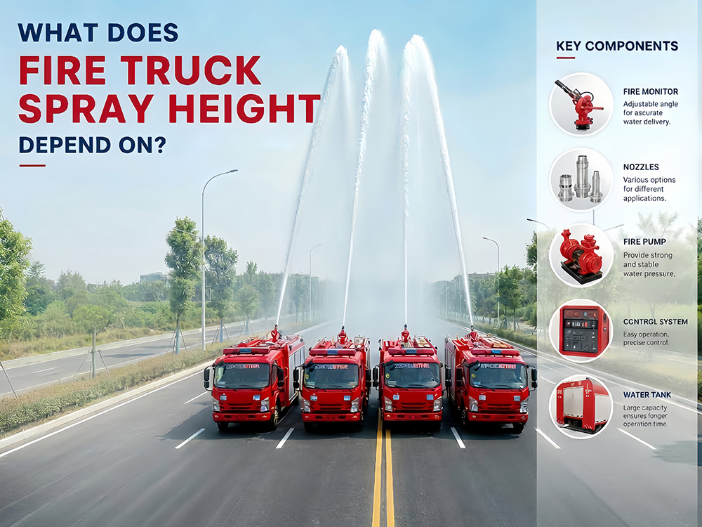
Sistem pam dan semburan trak bomba ialah teras operasi pemadaman kebakaran. Ia bertindak sebagai "lengan berkuasa" trak bomba. Dengan menukar kuasa enjin kepada tekanan (antara 0.8 hingga 1.4 MPa), ia menghantar bahan pemadam kebakaran ke ketinggian sehingga 85 meter — sama ada kebakaran bangunan tinggi di pusat bandar yang padat atau kebakaran tangki penyimpanan petrokimia di zon perindustrian, trak bomba bergantung pada sistem ini untuk mencapai pemadaman kebakaran yang berkesan. Apakah faktor yang mempengaruhi ketinggian semburan trak bomba, dan bagaimana tekanan pam, kadar aliran, serta pemantau kebakaran berfungsi bersama? Inilah perkara yang menjadi tumpuan ramai pelanggan. Mari kita pelajarinya hari ini. » I. Tiga Komponen Utama Yang Menentukan Ketinggian Semburan 1. Sistem pam bomba: Jantung trak bomba. Pam empar digerakkan oleh PTO. Gred tekanan biasa: 0.8 MPa, 1.0 MPa, 1.2 MPa, 1.4 MPa. Kadar aliran daripada 2,000 hingga lebih 5,000 L/min. 2. Pemantau kebakaran: Komponen terakhir sebelum bahan pemadam kebakaran keluar dari trak. Tersedia dalam pemantau air, pemantau buih, dan pemantau dwiguna. Siri PL (PL48) dengan kadar aliran sehingga 4,000 L/min dan ketinggian semburan sehingga lebih 70 meter. 3. Sistem penghantaran: Paip, hos, dan muncung yang membawa bahan pemadam kebakaran dari pam ke pemantau. Diameter hos, panjang, dan jenis muncung semuanya mempengaruhi ketinggian semburan akhir. » II. Faktor Teras Yang Menentukan Ketinggian Semburan 1.1. Tekanan Pam Tekanan pam trak bomba ialah daya yang dijana oleh pam bomba untuk menolak bahan pemadam kebakaran melalui hos dan mengeluarkannya dari muncung atau pemantau. Ia merupakan pemacu utama bagi kadar aliran dan jarak semburan. Tekanan yang lebih tinggi menghasilkan halaju yang lebih tinggi pada saluran keluar pemantau, sekali gus meningkatkan ketinggian semburan secara langsung. Hubungan ini dikawal oleh formula H ≈ P/(ρg), di mana setiap peningkatan 0.1 MPa menambah kira-kira 10 meter ketinggian teori — tetapi kehilangan sebenar mengurangkannya. Dalam operasi pemadaman kebakaran sebenar, julat berikut digunakan: Tekanan Pam Ketinggian Semburan Biasa 0.8 MPa 35–45 meter 1.0 MPa 45–55 meter 1.2 MPa 55–70 meter 1.4 MPa 70–85 meter 1.2. Cara pam bomba berfungsi: Pam biasanya merupakan pam empar yang digerakkan oleh enjin trak melalui pelepas kuasa (PTO). Apabila pendesak berputar, ia menarik masuk bahan pemadam kebakaran dan menolaknya keluar melalui daya emparan, menghasilkan tekanan yang menggerakkannya melalui sistem pelepasan. Tekanan Berkadar berbanding Tekanan Operasi: Istilah Definisi Tekanan Berkadar Tekanan maksimum yang boleh dikekalkan secara berterusan oleh pam di bawah keadaan reka bentuk Tekanan Operasi Tekanan sebenar yang digunakan semasa pemadaman kebakaran, biasanya lebih rendah daripada tekanan berkadar untuk menyediakan margin keselamatan 2. Kadar Aliran (L/min) Aliran yang mencukupi adalah sama penting dengan tekanan. Tekanan tinggi dengan aliran rendah tidak dapa...
Perincian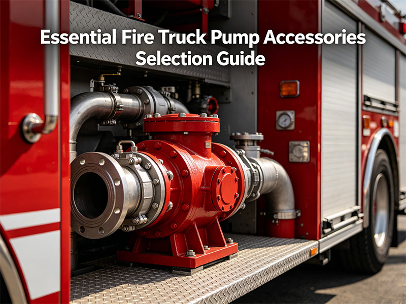
Sistem pam trak bomba hanya boleh dipercayai sebagaimana komponen-komponennya. Daripada menarik air daripada sumber hingga mengeluarkannya pada tekanan tinggi, setiap aksesori memainkan peranan penting. Panduan ini merangkumi trak bomba lima kategori aksesori utama: pemula, injap bebola, injap glob, pengadun perkadaran buih, dan sistem kawalan hidraulik. Memahami komponen ini membantu anggota bomba menyelenggara peralatan mereka dan memilih aksesori yang sesuai untuk aplikasi tertentu. I. Siri Pemula (Peranti Penyebuan Vakum) Pemula adalah penting untuk menarik air daripada tasik, sungai, atau sumber statik lain apabila pili bomba tidak tersedia. Ia mengeluarkan udara daripada pam dan hos sedutan, membolehkan tekanan atmosfera menolak air masuk ke dalam pam. Gambaran Keseluruhan Produk Produk Vakum Maksimum Voltan Kuasa Saiz Pam yang Sesuai pemula 2 omboh >85kPa 24V - Di bawah 100 L/s Pemula elektrik 2 omboh >85kPa 24V 2.1KW Di bawah 100 L/s pemula 4 omboh >85kPa 24V - Melebihi 100 L/s Pemula elektrik 4 omboh >85kPa 24V 2.1KW Melebihi 100 L/s Ciri Utama: Pemula Elektrik Pemula elektrik menawarkan kelebihan yang ketara — ia boleh menyebukan pam tanpa pam berputar. Ini melindungi pengedap mekanikal daripada kerosakan akibat operasi kering. Apabila pemula standard memerlukan pam berputar, versi elektrik berfungsi secara bebas, memanjangkan hayat pengedap. II. Siri Injap Bebola (Kawalan Aliran) Injap bebola mengawal aliran air melalui hos dan saluran keluar pelepasan. Ia direka untuk operasi hidup/mati pantas dengan pusingan mudah 90°. Injap Bebola Keluli Tahan Karat Model Bahan Tekanan Berkadar Benang Operasi FQS65/2.5 Badan & bebola: keluli tahan karat 304; Pengedap: PTFE 2.5 MPa G2-1/2" Roda tangan / Tuas FQS80/2.5 Badan & bebola: keluli tahan karat 304; Pengedap: PTFE 2.5 MPa G3" Roda tangan / Tuas Injap Bebola Aloi Aluminium (Berat lebih ringan) Model Bahan Tekanan Nominal Benang Operasi FQS65/2.5 Badan: A356.2; Bebola: 304; Pengedap: PTFE 2.5 MPa G2.5" Roda tangan / Tuas FQS80/1.6 Badan: A356.2; Bebola: 304; Pengedap: PTFE 1.6 MPa G3" Roda tangan / Tuas FQS65/2.5 Segi empat Badan: A356.2; Bebola: 304; Pengedap: PTFE 2.5 MPa - Pneumatik / Tuas Ⅲ. Siri Injap Glob (Pelarasan Tekanan & Aliran) Tidak seperti injap bebola yang direka untuk operasi buka/tutup, injap glob membolehkan kawalan tepat terhadap kadar aliran dan tekanan. Ia sesuai untuk keadaan yang memerlukan pelarasan berperingkat. Model Bahan Tekanan Nominal Benang Operasi DN65/2.5 Badan: A356.2; Batang: H62; Pengedap: NBR 2.5 MPa G2.5" Roda tangan DN80/2.5 Badan: A356.2; Batang: H62; Pengedap: NBR 2.5 MPa G3" Roda tangan Bila Menggunakan Injap Globe Gunakan injap globe pada titik pelepasan yang memerlukan kawalan tekanan halus, seperti ketika mengisi tangki kenderaan lain atau membekalkan talian hos pada tekanan tertentu. IV. Siri Perkadaran Buih (Peralatan Pencampuran Buih) Perkadaran buih mencampurkan pekat buih dengan air pada nisbah yan...
Perincian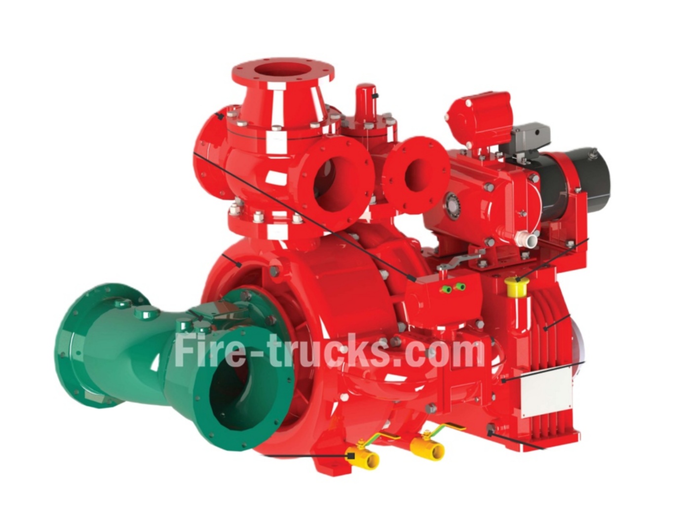
Sebagai seorang xiongzhen profesional pengeluar pam kebakaran di China, Trak Powerstar memiliki siri produk jenama sendiri "Xiongzhen", termasuk pam bomba tekanan rendah, pam bomba tekanan sederhana rendah, dan pam bomba tekanan tinggi rendah yang dipasang pada kenderaan, serta peralatan sokongan seperti pemantau kebakaran dan pengatur busa. Pam bombanya menggunakan bahan baharu seperti aloi aluminium dan keluli tahan karat, dan dilengkapi dengan peranti penyingkiran automatik klac elektromagnet dan injap sehala, yang menampilkan prestasi cemerlang, operasi mudah, dan penyelenggaraan yang mudah. Produk syarikat telah lulus ujian jenis oleh Pusat Penyeliaan dan Pemeriksaan Kualiti Peralatan Kebakaran Kebangsaan, pensijilan CCC, dan pensijilan sistem pengurusan kualiti ISO9001. Pam bomba Xiongzhen terutamanya merangkumi model berikut: CB10/20-XZ, CB10/30-XZ , CB10/40-XZ, CB10/60-XZ , CB10/80-XZ, CB10/100-XZ, CB20.10/15.30-XZ, CB20.10/20.40-XZ, CB20.10/30.60-XZ, dsb. PAM BOMBA CB10/20-XZ untuk trak bomba PAM BOMBA CB10/30-XZ untuk trak bomba Pam bomba Model CB10/40-XZ untuk jentera bomba China Pam bomba Model CB10-60 untuk trak penyelamat kebakaran Pam Bomba Kecemasan CB10/80-XZ untuk trak bomba Pam pemadam kebakaran CB10/100-XZ untuk kenderaan bomba Spesifikasi Sistem Pam Kebakaran xiongzhen CB10/100-XZ Pengilang Pam Kebakaran siri xiongzhen CB Spesifikasi Set Pam Bomba CB10/150 Sistem Pam Pemadam Kebakaran CB10/160-XZ kilang xiongzhen Spesifikasi Pam Kebakaran Kecemasan CB10/170-XZ Trak Powerstar mempunyai keupayaan teknikal yang kukuh, memegang empat paten, dan menggunakan peralatan pengeluaran canggih seperti penggubalan CAD dan peralatan mesin CNC untuk memastikan kadar kelayakan produk yang tinggi dan kepuasan pelanggan. Produknya disasarkan terutamanya kepada loji pengubahsuaian trak bomba dan pasukan bomba. Butiran spesifikasi pam bomba CB20.10 20.40 Pam Bomba CB20.10 30.60-XZ oleh kilang xiongzhen Pam kebakaran siri CB20/15-XZ pam kebakaran kecemasan siri CB20/20-XZ Butiran Pemasangan Pam Kebakaran CB20 25 Berikut ialah jadual penyelenggaraan untuk XIONGZHEN anda pam bomba , dikategorikan mengikut minggu, bulan, suku tahun dan tahun untuk rujukan mudah: 01, Pemeriksaan Harian Pam Bomba Powersar: Periksa tekanan mula-henti dan frekuensi pam penstabil tekanan. Periksa kuasa bateri penghidup pam bomba enjin diesel. Periksa rupa injap kawalan sumber air dan pemasangan injap penggera untuk kerosakan. 02, Pam Bomba Powersar Pemeriksaan Mingguan: Uji jalankan pam bomba motor penghidup automatik. Periksa paras bahan api pam bomba enjin diesel. 03, Pam Bomba Powersar Pemeriksaan Bulanan: Uji jalankan motor penghidup manual pam bomba dan pam bomba enjin diesel. Periksa paras air tangki air bomba dan tangki air bomba yang dinaikkan. Periksa tekanan udara, paras air dan isipadu berkesan tangki tekanan. Periksa integriti pengedap dan rantai semua injap kawalan sistem. Periksa perbezaan tekanan pencegah aliran balik. 04, Pam Bomba Powersar Pemeriksaan Su...
Perincian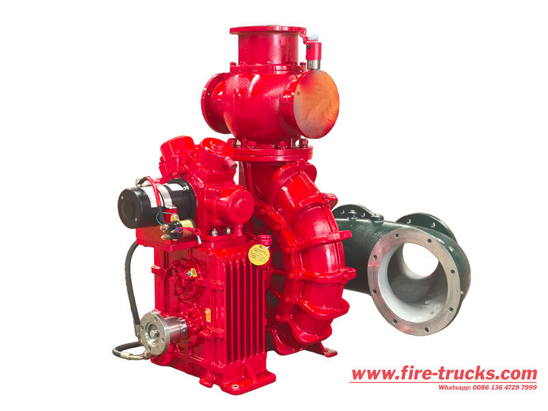
Pam pemadam kebakaran buih CB10/140 ialah sistem bekalan air kebakaran yang dipasang pada kenderaan atau pegun yang biasa digunakan dengan tekanan undian 1.0 MPa dan kadar aliran undian 140 L/s, memenuhi keperluan bekalan air teras sistem pemadam kebakaran. Badan pam dan pendesak dibina daripada bahan berkualiti tinggi dan tahan haus, menawarkan rintangan kakisan dan rintangan tekanan tinggi. Ia mempunyai reka bentuk dwi-saluran masuk untuk pensuisan sumber air yang pantas dan dipacu oleh motor atau enjin diesel berkecekapan tinggi, mencapai masa tindak balas permulaan selama 30 saat atau kurang. Dengan reka bentuknya yang padat, penyelenggaraan yang mudah dan operasi yang boleh dipercayai, Pam pemadam kebakaran busa CB10/140 merupakan peralatan penting bagi memastikan bekalan air yang cekap untuk operasi memadam kebakaran. Pam bomba yang dipasang pada trak tekanan rendah CB10/140-XZ mempunyai struktur emparan satu peringkat dengan selongsong pam aloi aluminium dan pendesak tembaga. Ia menggunakan sistem penyebuan air empat omboh elektrik dengan pensuisan elektrik. Pam buih CB10/20 pilihan menggunakan mekanisme pemisahan pneumatik. Produk ini menawarkan prestasi cemerlang, struktur padat, operasi mudah dan penyelenggaraan mudah. Pam bomba CB10/140-XZ ialah pam air emparan satu peringkat yang digunakan dalam trak bomba, dicirikan oleh peranti penyebuan dua omboh yang secara automatik mengaktifkan dan melepaskan. Ia direka bentuk untuk prestasi tinggi dengan struktur padat, operasi mudah dan penyelenggaraan yang mudah. Spesifikasi utama termasuk kadar aliran \(140\) L/s dan tekanan keluar \(1.0\) MPa pada kelajuan undian \(2600) r/min. » . Prinsip kerja pam pemadam kebakaran busa CB10/140 ● Pengambilan air dan pekatan buih: Air diambil daripada bekalan, dan busa pekat diambil daripada tangki simpanannya. ● Perkadaran: Alat pengatur mencampurkan pekatan busa dengan air pada nisbah yang telah ditentukan. ● Tekanan: Pam itu memberi tekanan kepada campuran, meningkatkan halaju dan tekanannya. ● Pelepasan: Larutan buih bertekanan ditolak melalui hos pelepasan ke muncung, di mana ia dinyahcas ke atas api. ● Penindasan kebakaran: Buih tersebut menyelimuti sumber bahan api, memisahkannya daripada oksigen dan memadamkan api. » . Pengenalan terperinci pam pemadam kebakaran buih CB10/140 1. Reka Bentuk Struktur Superior, Prestasi Stabil dan Boleh Dipercayai: ● Yang Pam bomba CB10/140 mempunyai reka bentuk emparan satu peringkat dan dibina daripada aloi aluminium berkekuatan tinggi, menawarkan kelebihan seperti ringan, rintangan kakisan dan rintangan suhu tinggi. ● Struktur dalaman pam dimesin dengan tepat, memastikan aliran yang lancar dan prestasi hidraulik yang cemerlang. Pengedap mekanikal menghalang kebocoran dan memastikan kebolehpercayaan operasi jangka panjang. ● Pam bomba ini mempunyai kapasiti sedutan dan pelepasan yang berkuasa, menjadikannya sesuai untuk pelbagai kenderaan pemadam kebakaran bersaiz sederhana dan besar serta peralatan pemadam kebaka...
Perincian
Sila baca selanjutnya, terus berhubung, langgan, dan kami mengalu-alukan anda untuk berkongsi pendapat anda.

 Rangkaian IPv6 disokong

 Melayu
 English
 français
 Deutsch
 русский
 italiano
 español
 português
 Nederlands
 العربية
 日本語
日本語 한국의
한국의 Türkçe
 ไทย
ไทย Tiếng Việt
 Indonesia
  中文
中文 қазақ
қазақ Filipino
 မြန်မာ
 српски